

Setting the groundwork for developing acoustical data to keep pace with advances in firestop joint systems.
Introduction
Fire resistance and acoustics come to a crossroads at head-of-wall joint systems. For such joint systems it is often necessary to have a measure of both fire safety performance and acoustic performance. Recent innovations with firestop materials have created a scenario where acoustics consultants and designers are presented with joint systems that may not match historical sound test data. Consequently, the number of acoustic tests required to enable evidenced-based designs has increased in recent years. While fire resistance testing has a distinct option for allowing small-scale testing of joint systems, acoustics testing in North America currently does not. The small-scale testing approach has allowed firestop joint systems to dynamically grow with the increase in product innovations. To allow acoustics testing to do the same, a small-scale acoustics test for joints would need to be developed and adopted for use in North America. The methods of ISO 10140-1 Annex J could potentially serve as the basis for such a small-scale test.
Defining the methodologies for fire resistance and acoustics testing is necessary to set the stage for understanding the need for small-scale acoustics testing for joint systems. Testing performed by Veneklasen Associates, Inc. and Hilti Inc., investigated the suitability of an already existing small-scale acoustics test methodology (the cassette) for anticipating large-scale results. These testing activities have involved laboratory testing of multiple firestop products, multiple steel-framed gypsum wall configurations, and includes field testing. The confluence of positive results demonstrates the validity of pursuing adoption of a cassette methodology for acoustics. The results also those that Hilti firestop products succeed at maintaining the acoustic performance of a joint system using the existing test method of ASTM E90.
During this journey to investigate a suitable small-scale acoustic test method for joints it is also possible to address whether it is reasonable to expect head-of-wall joint systems to perform the same as base walls (walls without a joint) for acoustic results. A corollary between thermal isolation and acoustic isolation during the testing of base walls indicates that a joint is a unique condition the performance of which should be taken relative to other joints. The goal is to maintain harmony between ratings for base walls and ratings for joints. These ratings should not necessarily be the same due to the differences in how they are obtained.
Testing Requirements and Methodology
Fire Resistance
Fire resistance testing has well defined criteria within model building codes including the International Building Code (IBC), the National Fire Protection Association (NFPA) Life Safety Code, and the National Building Code of Canada (NBC). It can be broken down into many categories, and of these, this paper will focus on two. The first is fire-resistance ratings for assemblies, and the second is fire-resistant joint systems. IBC sections described below are in reference to the 2018 IBC.
The most well-known requirement is for fire-resistance ratings of assemblies. This refers to the hourly ratings assigned to walls, floors, beams, columns, and other building elements. According to IBC Section 703.2, either ASTM E119 or UL 263 shall be used to determine fire-resistance ratings of building elements, components, or assemblies. UL 263, Edition 14, will be used in this paper to refer to these testing requirements. The main point is that UL 263 assigns ratings to singular building elements.
Fire-resistant joint systems can be regarded as assigning ratings to combinations of building elements. IBC Section 715.1 starts with, “Joints installed in or between fire-resistance-rated walls, floor or floor/ceiling assemblies and roofs or roof/ceiling assemblies shall be protected by an approved fire-resistant joint system designed to resist the passage of fire.” These joint systems must resist fire passage for a duration that matches the fire-resistance rating of the assemblies. IBC Section 715.3 requires that ASTM E1966 or UL 2079 be used to test fire-resistant joint systems. UL 2079 will be used to refer to this requirement throughout the remainder of this paper.
Table 1 is used to compare the different test methodologies UL 263 and UL 2079. The goal of explaining only select details from these standards is to understand the requirements for setting up the test and give a high-level overview of acceptance criteria.
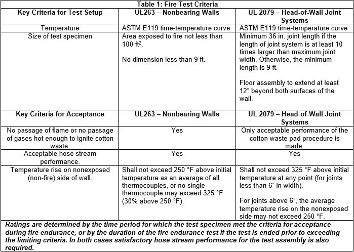
While there are many more details involved with UL 263 and UL 2079, the features above show the two standards have similar performance criteria while allowing differences between the minimum size of test specimens. Small-scale testing for fire-resistant joint systems can be done in smaller furnaces and with smaller test assemblies while maintaining the same stringent performance thresholds that are required at full scale. This lowers to opportunity costs to test fire resistance joint systems for secondary performance criteria, namely air-leakage ratings and movement.
The next topic to consider are the methods used to isolate the wall assembly in UL 263, and the joint assembly in UL 2079, so that edge effects do not impair the test results. The term edge effect refers to the fact that materials will perform differently under fire conditions when interfacing with dissimilar materials. As an example, it is expected that the temperatures at the interface between gypsum board and concrete will be different than the temperatures on the concrete and gypsum a distance from this interface. The goal of UL 263 is to evaluate the performance of the material on its own, and to prevent edge effects from influencing the results. For UL 263, the outer 12 inches, sometimes more for larger assemblies, of the test specimen do not require any temperature measurements and are effectively removed from consideration for acceptance criteria. Interfaces between the test assembly and the frame of the furnace are then protected with a material that prevents heat loss at these interfaces. In most cases, this protective material is ceramic insulation in conjunction with a lip on the furnace frame that overlaps onto the test assembly. The ceramic insulation is tightly wedged between the frame and test assembly around the entire periphery of the assembly as depicted in Figures 1 and 2 below. The interface between the test specimen and the furnace is thermally isolated. Thermal isolation, in this case, means that the amount of heat that is transferred through the protected interface is orders of magnitude less than the amount of heat transferred through the test specimen itself and impact on tests results will be negligible.
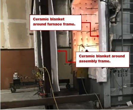
Figure 1: UL 263 Wall Assembly and Furnace, Before Fire Endurance (Ref.1)
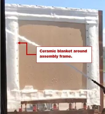
Figure 2: UL 263 Wall Assembly, Post Fire Endurance, During Hose Stream (Ref.1)
For UL 2079, a similar procedure is used to isolate the periphery of the test specimen. The key difference with joint systems is that the joint in consideration is not thermally isolated. The goal of the test is to determine the performance of the joint in question. For head-of-wall joints, this means that the joint between the wall assembly and floor assembly is exposed to the fire endurance conditions as seen in Figure 3 below. Therefore, it is necessary to install some type of firestop material within this joint to ensure the conditions for acceptance are met.
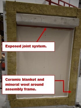
Figure 3: Head-of-Wall Joint System Between Gypsum Wall and Concrete Floor. Courtesy of Hilti Inc.
Acoustics
Even without code requirements, ASTM E90 is firmly established as a consensus standard used to evaluate acoustic performance in North America. The key metric obtained from ASTM E90 is the Sound Transmission Class (STC). The STC value is what the design community uses to compare the relative acoustic performance of different assemblies.
Model code requirements for sound are limited when compared to requirements for fire-resistance ratings. The 2018 International Building Code (IBC) Section 1206 is the most cited requirement for sound transmission in North America. The STC value is to be determined by ASTM E90, Standard Test Method for Laboratory Measurement of Airborne Sound Transmission Loss of Building Partitions and Elements (ASTM E90) in accordance with Section 1206.2. IBC Section 1206.2 requires a minimum STC of 50 in select cases where building elements are separating dwelling or sleeping units.
On one hand ASTM E90 is used to evaluate sound transmission through walls proper, while on the other hand it is used to assess sound transmission through head-of-wall joints. A close look at the ASTM E90 test setup will improve understanding of the difference between testing for the wall and testing for the joint. It should first be repeated that there is not a separate acoustic test standard for joints. Compared to fire testing which relies on ASTM E119/UL 263 to determine the fire-resistance rating of the building element and UL 2079 to determine the fire-resistance rating of the joint system, acoustic performance for building elements and for joints between building elements is determined by a single standard, ASTM E90, in North America
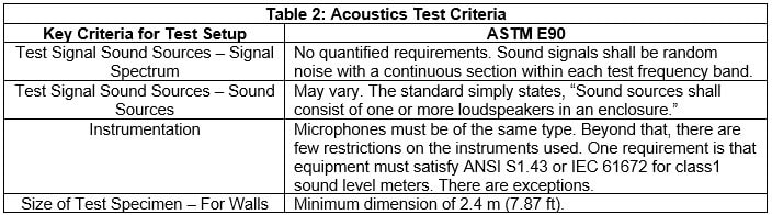
It is easy to imagine that the limited constraints for ASTM E90 may lead to variations between tests and between testing laboratories. This is precisely what happens. Dong et. al (2020) discuss that the ASTM reference assembly has a standard deviation of 3 dB at upper frequencies. Such deviation results only apply to wall assemblies and do not begin to consider variations that can occur when introducing a head-of-wall joint system to the test. It is not surprising to find results from different laboratories, or in the same laboratory but from different times, that show differences with the same joint system.
Laboratory Acoustics Testing
Veneklasen Associates, Inc. (Veneklasen) conducted a series of tests to quantify the difference in acoustical performance between traditional and new joint-sealing methods. In all cases the testing involved a head-of-wall joint for a framed gypsum wall assembly. The traditional joint-sealing method involved the use of a non-hardening firestop sealant, Hilti CP 606 Flexible Firestop Sealant (see Figure 4 below) The new method involved Hilti CFS-TTS Firestop Top Track Seal installed over the ceiling runner (see Figure 5 below) of the gypsum wall and as a backer-rod in the joint (see Figure 6 below).

Large-Scale Testing - Setup
Procedures and requirements of ASTM E90 were fulfilled during large-scale testing. For each test the following details were observed:
· Wall specimen dimensions were 8-ft. by 8-ft. (2.4m x 2.4m).
· Wall construction involved the following elements:
o 3-5/8 in., 25 gauge steel studs. Studs spaced 24 in. on center.
-Both double-stud and single-stud wall configurations were considered.
o Batt insulation in cavity of studs.
o Gypsum board, 5/8 in. thick, type X.
-Upper-most section of gypsum board was removed in order to facilitate modification of the joint condition.
The lower pieces of gypsum board remained in place between tests to minimize variations between tests.
-Number of layer of gypsum board varied as detailed in Table 3.
o Sound isolation putty around the bottom and sides of specimen were left in place.
The top of the wall had sound isolation putty installed in those instances where a baseline value for the wall was taken,
but when testing to joint system the sound isolation putty was removed from the top of the wall.
Additionally, the test specimen was protected against edge effects. This is identical to the treatment of an assembly undergoing fire testing in accordance with UL 263. The assembly is acoustically isolated around the periphery of the assembly in order eliminate the influence of edge effects, i.e. the interface between the assembly and test frame. For acoustic isolation it is very common practice to use what is called duct seal putty as depicted in Figure 7 below.
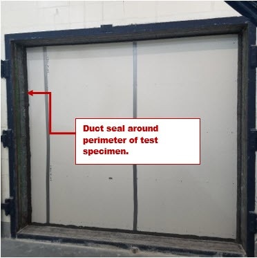
Figure 7: ASTM E90 Test Setup, Gypsum Wall To Concrete Header. Courtesy of Hilti Inc.
Comparing Figure 2 and Figure 7 it is clear the test specimens are designed to isolate the effects from the joint between the specimen and the test chamber or frame. For ASTM E90 testing of base walls the duct seal putty is installed along the entire perimeter.
When testing the head-of-wall joint in accordance with ASTM E90 the best practice is to run a test for the base wall and a test for the joint system. To avoid ancillary effects from reconstructing the wall, which we see above can yield different results for the same wall type, the wall is constructed along with the joint system to be evaluated. For a pre-installed joint system the only adjustment needed to test the joint system is to remove the duct seal putty (see Figure 8 below).
For joint systems using sealant it is more likely to install the sealant after the base wall testing and removal of the duct seal putty along the joint. However, there are details which can affect the results. Sometimes additional duct seal putty is placed in the joint itself to combine with the putty ran along the joint surface, which amounts to having two joint systems serving as acoustic isolation. On the other hand, if the duct seal putty was placed only to cover the joint on the surface of the wall, leaving the joint gap empty, this would serve to lower the performance of the base wall. In this situation when sealant in the joint is then substituted for duct seal on the surface of the joint, the relative performance of the sealant joint versus the base wall would look artificially better compared to the previous case.
It is critically important to understand the implications for pre-installed joint systems. The base wall is tested with two systems that serve as barriers to sound transmission. The first is the joint system itself at the joint to be evaluated. At other interfaces between the wall and test frame the wall material, such as gypsum board, is butted to the frame. The second system is the duct seal putty. It is this nuance in test methodologies which warrant caution to the expectation that joint systems perform acoustically the same as the base wall with regards to STC ratings. This is because the base wall is tested such that all joints are acoustically isolated. For joint systems that use pre-installed methods, the acoustic isolation is in the form of two joint systems.
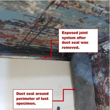
Figure 8: ASTM E90 Setup of a Head-of-Wall Joint System, Duct Seal Removed from Joint. Courtesy of Hilti Inc.
Large-Scale Testing - Results
Table 3 summarizes the full-scale testing conducted.

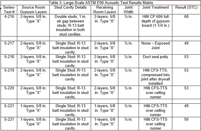
Based on the results of full-scale testing, the following general conclusions are made:
1. Comparison of the fully caulked joint (CP 606) with joints covered in duct seal show no variation between the two methods. Therefore, it is reasonable to take results for tests involving duct seal as being valid for a joint filled with CP 606 and vice-versa for the data presented above.
2. Differences between joints acoustically treated with duct seal and joints with Hilti CFS-TTS were small. As expected, the differences increased as the STC performance of the wall increased. In many cases the final STC values were the same for both acoustically isolated joints and joint with Hilti CFS-TTS installed.
Small-Scale (Cassette) Testing - Introduction
Standards designed to measure the sound through a gap as found with the joint at the top of a wall do not exist for North America. Neither ANSI, nor ASTM currently have a standard method for testing this condition. There is a common notion that ASTM E90 provides this measurement whenever the joint in question is exposed. However, the calculations involved with reporting the STC value based on ASTM E90 data results in a value of sound transmission loss per unit area of a test specimen.
What is needed for joints is a method that allows calculation of sound transmission loss per unit length of a joint. One potential method exists with the provisions of ISO 10140-1 Annex J. ISO 10140-1 Annex J.1 reads, “This annex is applicable to acoustic sealing of slits (with or without fillers) and of gaps or joints between parts of windows or doors”. This standard is popular outside of North America, particularly in Europe. The test program conducted for this study was designed to meet the following goals:
· Evaluate ISO 10140-1 Annex J test method to determine if it yields consistent and accurate results.
· Using the results of cassette testing to predict the STC rating of a full-sized test specimen.
· Compare Hilti CFS-TTS Top Track Seal to traditional sealant methods using the cassette methodology.
The idea is to demonstrate that the methods of this test can be adopted to provide reliable data for head-of-wall joints and to investigate the correlation between this method and ASTM E90.
Small-Scale (Cassette) Testing - Setup
A first step for cassette testing is to construct what will be termed a “filler wall”. This filler wall serves to reduce the effective size of the sound chamber to the size of the cassette. In this way, measurements for sound reduction are based on the performance of the cassette only. ISO 10140-1 Annex J.2.3 provides general guidance for the filler wall (see Figure 9).
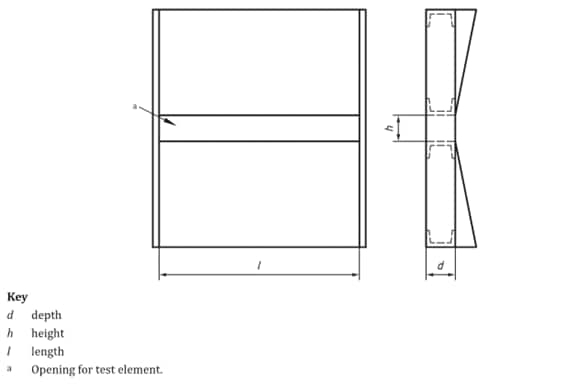
Figure 9 – ISO 10140-1 Figure J.3
The second step in setting up the small-scale testing was to design a cassette. The language in ISO 10140-1 Section J.3.2 does not place restrictions on the cassette size, except to stipulate that the cassette should fit into the framed opening of the filler wall constructed. To ensure integrity of the test method, preliminary tests were conducted in cassettes of different lengths. Two lengths of cassettes were examined that resulted in the following joint widths: 46.0 in. (1.17 m), the single cassette, and 92.1 in (2.34 m), the double cassette. The full width of the cassettes was 47.2 in. (1.2 m) and 94.5 in. (2.4 m) respectively. Note that separate filler walls were built to handle the two different lengths of cassettes examined.
For each cassette length Hilti CFS-TTS, Hilti CP 606, and duct seal putty were examined. The data from these tests was evaluated by Dong et al. (2020) with the conclusion that the length of the cassette does not have a material effect on the results concerning the lengths tested. The conclusion was reached by comparing the difference in transmission loss between the two cassette lengths and finding that within the frequency range of interest, 500 Hz to 5000 Hz, the difference was within one dB as shown in Figure 10.
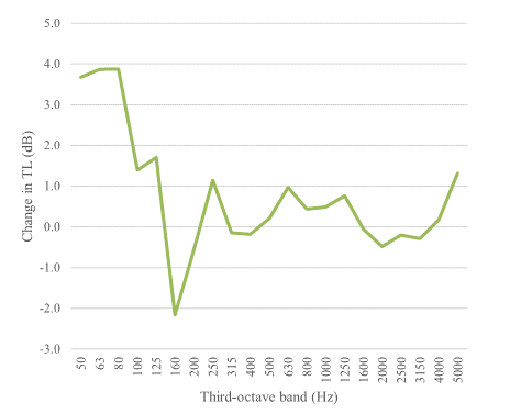
Figure 10 – Transmission Loss Difference Between Double and Single Cassettes (Ref. 3)
With initial investigations validating the test methodology, a cassette length of 47.2 in. (1.2 m), resulting in a joint length of 46.0 in. (1.17 m) was chosen for the test program. This allowed dimensions for the filler wall to be determined. Photos of the filler wall are detailed in Figures 11 and 12.
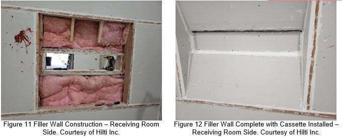
Cassette testing used the same signal source and instrumentation as testing for the large-scale tests. Construction began with a frame made of plywood. Inside of the frame a steel-stud gypsum wall was constructed. The gypsum wall consisted of the following details:
· 3-5/8 in., 25 gauge steel studs. One stud was placed at the center of the cassette. On each side of the center stud, the adjacent studs were at 24” oc. The remainder of the studs were located at the ends of the cassette frame.
o Only single stud configurations were considered.
· Batt insulation in cavity of studs.
· Gypsum board, 5/8 in. thick, type X.
o Upper-most section of gypsum board was removed in order to facilitate modification of the joint condition. The lower pieces of gypsum board remained in place between tests to minimize variations between tests.
o Number of layer of gypsum board varied as detailed Table 4.
Small-Scale (Cassette) Testing - Results
The test program for the cassette method followed a similar approach as the large-scale tests by investigating different materials in the joint and comparing performance to acoustically isolated joints and empty joints. Tthe STC results for the cassette testing are based on sound loss per unit length of joint. Large scale STC test values are based on sound loss per unit area of the test specimen. To translate the data from the cassette testing, Equation 5 in ASTM E90 was modified as described by Dong et. al. (2020) to the following:

The cassette testing was found to be reliable in the 500Hz – 5000Hz range. The results of the cassette testing are presented in Table 4.
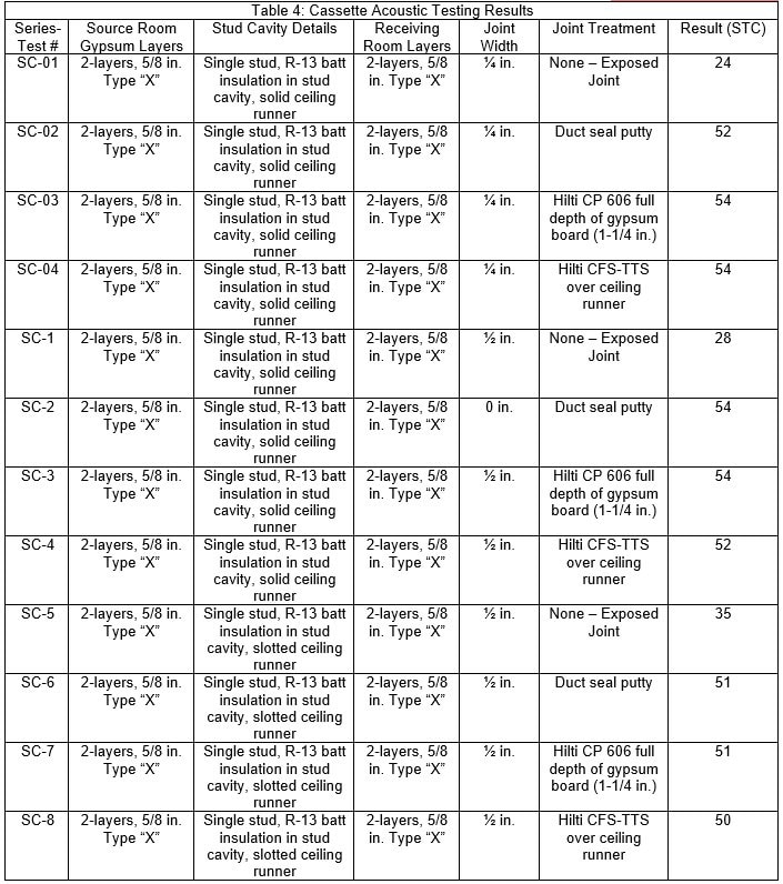

Table 4 provides cassette STC values for joints that are empty, acoustically isolated with duct seal putty, and joints with various firestop materials. Different joint widths were also tested. A maximum transmission loss value for the cassette configuration was established by testing four different cassettes. Then an average was found to allow comparison to the performance of firestop material in the joint. One such comparison is provided in Figure 13 from the study by Dong et. al. (2020).
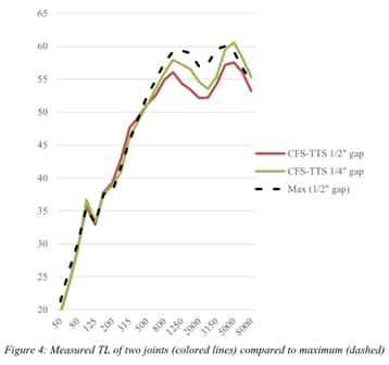
Figure 13: Maximum Sound Transmission Loss (TL) of Cassette vs. TL of Two Joints (Ref. 3)
Cassette testing yielded promising results with a few areas of improvement identified. The length of the cassette did not have a meaningful influence on the test results. The cassette testing proved easier to accomplish compared to the ASTM E90 setup and the contour of the STC curves between the cassettes and the full-scale walls were in harmony. An area for improvement is needed with regards to the reported magnitude of the results. The testing performed showed that the cassette underpredicted the performance of the full-scale wall. Additional investigation and adjustment to the calculation methods could help improve this deficiency. Figure 14 provides a comparison between the cassette results and the full-scale results for the corresponding wall.
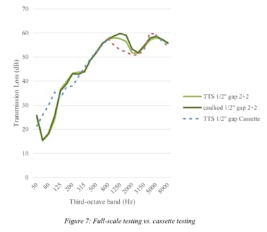
Figure 14: Transmission Loss Comparison Between Cassette and Full-Scale Wall (Ref. 3)
Concluding Remarks
The framework for a small-scale cassette method when measuring acoustic performance of joint systems is contained in ISO 10140-1. This test method was found to warrant further study and improvement. The small-scale cassette method will allow for more frequent testing of joint systems. It could also make acoustic test results more consistent for joint systems by isolating the results to a sound transmission loss per unit length of joint. Finally, having a small-scale test method for acoustic performance of joints would follow the same principles that allow for a small-scale fire test method for joints.
Acoustical performance of the joint systems tested with Hilti firestop products was exceptional. The joint systems tested represent systems that have also performed well for fire resistance. Having positive acoustic and fire resistance test results aids the design community in selecting joint systems that will meet the needs of the built environment.
It was seen that the procedures followed when conducting an ASTM E90 test for a base wall and for a wall with a joint system can cause different results, in the form of different STC values. Testing for base walls often results in multiple layers of acoustic isolation when using the same wall to test the joint system. Therefore, it is important to include all details of the test procedure along with the STC values so one can have context for the results presented.
Advancing the capabilities of acoustics testing is an exciting prospect. The cassette methodology would help to make comparisons between different joint configurations by reducing the impact of factors other than the joint itself. This method also lowers the opportunity costs and time needed for testing. While a laboratory may be able to test up to three ASTM E90 head-of-wall joint configurations, under the best of circumstances, it is easily possible to test eight cassettes in a single day. More cassettes could be tested if they were fully prepared beforehand, which would leave only the mounting of the cassette as the final installation step before testing. Most interesting is the possibility of cassette testing enabling laboratories to examine the effects of additional attributes found in fire-resistant joint systems, such as movement. It is possible to design a cassette that can allow the joint to undergo cycling at a fire test facility, where the width of joint is compressed and/or extended, and then send the cassette to an acoustics laboratory. This would enable acoustics and fire protection to gain complete alignment in an application critical to both life safety and the comfort of occupants, a key goal for Hilti Inc. and Veneklasen Associates, Inc.
References
1. Ashley Mcwatters. ASTM E119 Fire Test. YouTube 2018. https://www.youtube.com/watch?v=vO-PZs7k3JI (accessed October 11, 2022).
2. “ASTM E90, Standard Test Method for Laboratory Measurements of Airborne Sound Transmission Loss of Building Partitions and Elements,” ASTM International, West Conshohocken, PA, 2016.
3. Dong, Wayland, et al. (2020, Aug. 23). “Investigation of Methods to Evaluate Acoustical Effects of Top-of-Wall Joints.” [Conference Session]. Seoul Inter-Noise 2020 Conference, COEX Mall, Gangnam-gu, Seoul, South Korea.
4. International Code Council. (207). International Building Code. Falls Church, Va. International Code Council. Print.
5. “ISO 10140-1 (2016), Acoustics - Laboratory Measurement of Sound Insulation of Building Elements Part 1: Application Rules for Specific Products,” International Standards Organization, 2016.
6. Underwriters Laboratories INC. (2015). Standard for Tests for Fire Resistance of Building Joint Systems (UL 2079). Print.
7. Underwriters Laboratories INC. (2021). Fire Testing of Building Construction and Materials (UL 263). Print.
8. Underwriters Laboratories INC. (2015). Standard for Tests for Fire Resistance of Building Joint Systems (UL 2079). Print.
