
Development length provisions for post-installed rebar used in extension applications
The Canadian Standards Association (CSA) standard titled Design of concrete structures (CSA A23.3) includes provisions for reinforced concrete design. These provisions are written for cast-in reinforcing bar design; however, post-installed reinforcing bars that demonstrate equivalency to cast-in bars can also be designed for development with these provisions. This paper will discuss how the development and splice provisions given in CSA A23.3-19 Chapter 12 can be used to design post-installed reinforcing bars for a tension lap splice*.
CSA A23.3 Provisions for Tension Development
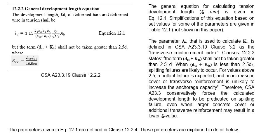
Reinforcing bars that are designed for “development” per CSA A23.3 provisions are designed to reach the specified yield strength (fy MPa) of the bar. CSA A23.3:19 provisions for tension development are predicated on bar installation with small concrete cover. Therefore, the bar must be embedded deep enough to preclude splitting failure and permit the bar to be “developed”, i.e. reach its yield strength. The embedment required to yield a bar is a calculated value that is referred to as the “development length” of the bar. The general equation given in CSA A23.3-19 for calculating tension development length (ld mm) is:

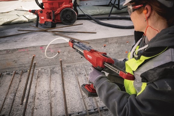
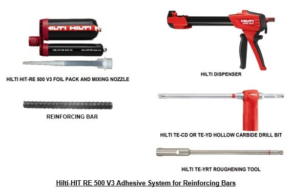
Reinforcing bars that are installed into hardened concrete using an adhesive product are referred to as “post-installed” reinforcing bars. The bars are part of an overall “adhesive anchor system” that includes the bar, adhesive product and installation procedure. The installation procedure consists of drilling a hole into a concrete member, removing drilling dust from the hole, injecting adhesive into the hole, and inserting the reinforcing bar into the hole such that the adhesive, when cured, will bond to both the concrete and the bar. The bond that develops between the adhesive and bar, and the adhesive and concrete, permits load applied to the bar to be transferred into the concrete member. The drilling method (e.g. hammer drilling or core drilling) as well as hole cleaning to remove drilling dust (e.g. blowing, brushing, etc.) are established during adhesive product evaluation via an accepted test program. The figure below shows components included in the Hilti HIT-RE 500 V3 adhesive anchor system for installation of post-installed reinforcing bars.
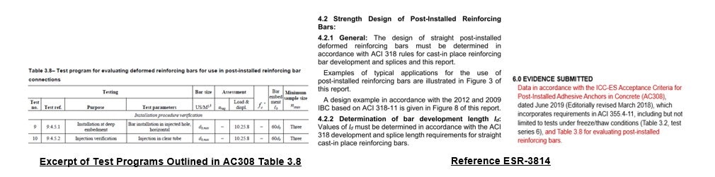
The International Code Council Evaluation Service (ICC-ES) writes what are known as “acceptance criteria”, to permit evaluation of products for recognition “in the opinion of ICC-ES” under the International Building Code (IBC). IBC recognition is provided via an ICC-ES evaluation report which is also known as an “ESR”. The ICC-ES also publishes evaluation reports known as “ELC’s” (Evaluation Listings for Canada) that include technical data where they are required by CSA and the National Building Code of Canada (NBC). To demonstrate compliance with the NBC, an evaluation of an adhesive anchor system in accordance with ACI 355.4 is necessary*. The ICC-ES acceptance criteria for evaluation of adhesive anchor systems in accordance with ACI 355.4 is titled Acceptance Criteria for Post-Installed Adhesive Anchors in Concrete Elements (AC308). Evaluation per AC308 also provides product-specific data and provisions that can be used to design the adhesive anchor system with limit states design provisions. Reinforcing bars successfully evaluated per the test program outlined in AC308 Table 3.8 can be post-installed as part of an adhesive anchor system in which the bars are designed using development and splice provisions (e.g. CSA A23.3-19 Chapter 12 provisions)*. Note that Canadian regulatory codes and standards remain silent on the evaluation and pre-qualification of post-installed rebar connections designed for development and splicing, therefore, no related data is published within an ELC. To design a rebar connection using CSA A23.3 Chapter 12 provisions, a product’s ESR should be referenced.
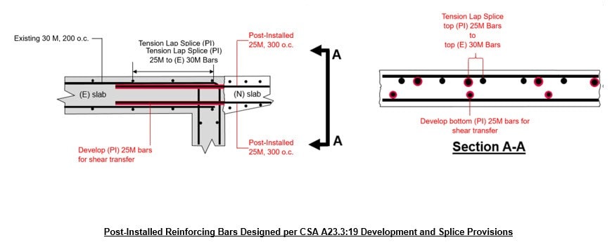
Post-installed reinforcing bars evaluated per the test program outlined in AC308 Table 3.8 can be designed using CSA A23.3 development and splice provisions in the same manner as a cast-in bar is designed using these provisions*. The illustration below shows an application for which the top post-installed reinforcing bars are being designed for a tension lap splice and the bottom post-installed reinforcing bars are being designed for tension development. The tension development length (ld mm) is calculated per CSA A23.3-19 Eq. (12.1) and the lap splice length is calculated per CSA A23.3:19 Clause 12.13.1.
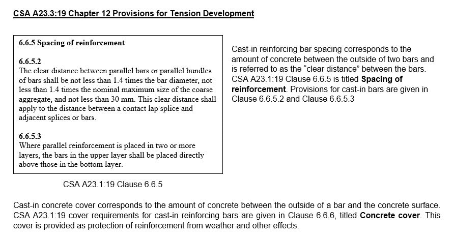
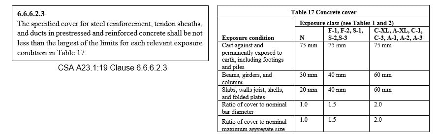
Cover and spacing requirements for post-installed reinforcing bars being designed for development are derived from product specific testing. Hilti adhesive products used with reinforcing bars being designed for development have been evaluated per the test program outlined in AC308 Table 3.8. The cover and spacing requirements derived from this testing are given in the ICC-ES evaluation report (ESR) for the adhesive product.
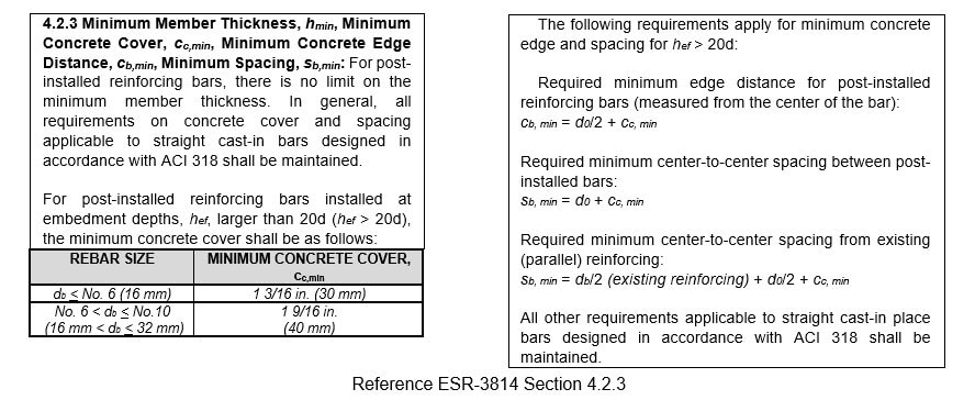
Below is an excerpt from ESR-3814 (HIT-RE 500 V3 adhesive) showing the cover and spacing requirements for post-installed reinforcing bars being designed for development. The test programs outlined in Table 3.8 of AC308 are predicated on a wider range bar embedment depth, including depths greater than 20-bar diameters (20db mm). As noted above, CSA A23.3 cover requirements are predicated on the amount of concrete between the outside of a bar and the concrete surface, and spacing requirements are predicated on the clear spacing between bars. It is important to note that cover requirements derived from AC308 evaluation are predicated on the distance from the center of the post-installed bar to the concrete surface, and spacing requirements derived from AC308 evaluation are predicated on the center-to-center spacing between bars. The parameter “d0” noted below corresponds to the drilled hole diameter (d0 mm) for the post-installed reinforcing bar, which is different than the bar diameter (db mm). Values for d0 are given in the ESR. Also note that the spacing requirements between two post-installed bars are different from the spacing requirements between a post-installed bar and an existing cast-in-place bar.
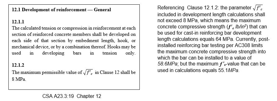
CSA A23.3:19 Chapter 12 contains provisions for development of cast-in reinforcing bars. These provisions will be explained below, keeping in mind that post-installed reinforcing bars qualified per the test program outlined in AC308 can also be designed with these provisions*. Any exceptions to these provisions with respect to post-installed bar design versus cast-in design will be noted. In the context of this paper, the discussion emphasis will be on those sections in Chapter 12 that are relevant to straight bar tension reinforcement designed for development.

CSA A23.3:19 Clause 12.5 includes provisions for designing a hook. Use of a hook for reinforcement design permits a bar to be developed when there is not enough concrete to develop a straight bar. Figure 1 shows the calculated straight bar tension development length (ld mm) for the red bars. This length is greater than the grade beam thickness of 36 in. Therefore, in order to develop the bars in tension, a 900 hook can be used. Figure 2 shows the hook length (ldh mm) that would be calculated per the provisions given in Clause 12.5 and the factors defined in Clause 12.5.3. When designing a post-installed reinforcing bar for development, only a straight bar can be installed in the hole that must be drilled into the existing concrete. Therefore, post-installed reinforcing bars cannot be designed with a hook at the end that is installed into existing concrete. However, a hook could be designed for the end around which new concrete will be placed.


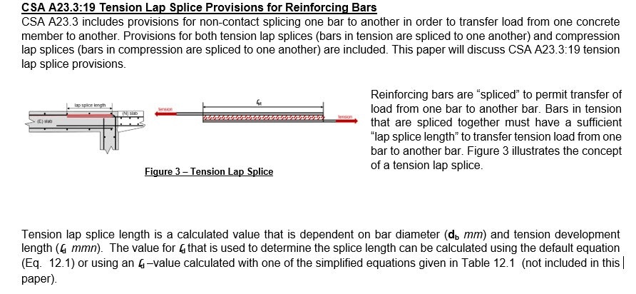
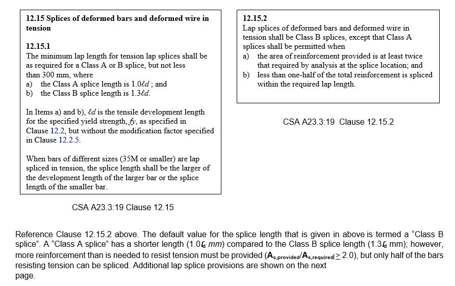
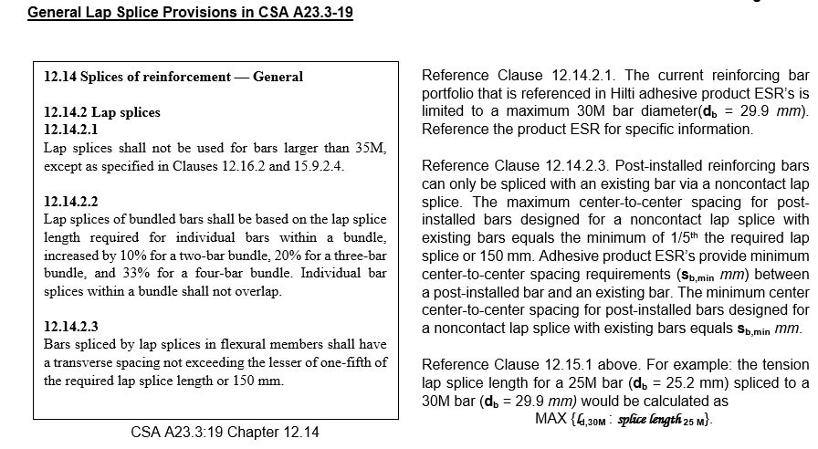
Designing Post-Installed Reinforcing Bars for Development per CSA A23.3-19 Provisions
As previously noted, reinforcing bars evaluated in conjunction with an adhesive product per the test program outlined in AC308 Table 3.8 can be designed using CSA A23.3 development and splice provisions (e.g. CSA A23.3-19 Chapter 12 provisions)*. The design procedure can be summarized as follows.
1. Verify that the adhesive product has been evaluated per the test program outlined in AC308 Table 3.8. Reference sections 4.2 and 6.0 in the adhesive product ESR.
2. Select a bar diameter and grade. Design the reinforcement per the provisions for the concrete member in which it will be utilized, e.g., CSA A23.3 Chapter 10 for a beam or a one-way slab, etc. If the design is satisfied, calculate the required development length, lap splice length, and detail the bars. Post-installed reinforcing bars can only be designed as a noncontact lap splice.
3. Develop an installation procedure for the post-installed bars that follows the Manufacturer’s Printed Installation Instructions (MPII). The installation procedure should also include location of existing reinforcement, drilling method (e.g. hammer drilled or core drilled), cleaning procedure and required gel/setting times for the adhesive.
Summary
Adhesive anchor systems that have been successfully evaluated per the test program outlined in Table 3.8 of the ICC-ES acceptance criteria AC308 demonstrate performance equivalency to cast-in reinforcing bars such that the post-installed bars can be designed using CSA A23.3 development and splice provisions*. The ICC-ES evaluation report (ESR) for Hilti adhesive systems will note if the adhesive product has been evaluated per AC308 Table 3.8. Reference Section 6.0 in the ESR.
*The evaluation of a post-installed reinforcing bar system as an alternative to cast-in-place reinforcing bars using the development length provisions of ACI 318 and CSA A23.3 is outside of the scope of ACI 355.4. The suitability of this application is evaluated under ICC-ES Acceptance Criteria AC308, Table 3.8.
Additional Resources
Design Guides
Hilti Post-installed Reinforcing Bar Design Guide
Hilti Post-installed Reinforcing in Fire Conditions Design Guide
Design Software
PROFIS Engineering
Hilti Post-Installed Rebar White Papers
* Post-installed Reinforcing Bar Design Options: An Overview
* Interface Shear Transfer Design using the Hilti Method for Post-installed Rebar Design
* Design for Yield using Anchoring-to-Concrete Provisions for Post-installed Reinforcing Bar Design
* Extension Design using CSA A23.3-19 Provisions for Post-installed Reinforcing Bar
* Structural Joint Design using CSA A23.3-19 Provisions for Post-installed Reinforcing Bar
* Designing Rebar in Fire-rated Concrete-to-concrete Connections: Frequently Asked Questions
* Designing Post-installed Rebar for Fire Conditions using PROFIS Engineering Whitepaper
